LIGHTED ’49 FORD PROJECT
Photos & Text by: Roy R. Sorenson
Lighting and battery technology has come a long way in the past few years and as a modeler I wanted to take advantage of the new technology. In the past if you wanted to light your model car you were forced to work with grain of wheat bulbs, big, bulky wires, and a 9 or 12 volt battery hidden in the base. But today we have LEDs, Nano Chips, fiber optics, etc. that can run for several hours on a small, flat, watch battery that you can hide inside a 1/25th scale model car! I wanted to be able to light a model car without all the bulky wires, and remote battery, and with the new technology I was able to fully wire the model, and you don’t see any of it! To understand the LED technology I visited Evan Designs the web (https:// evandesigns.com/) and checked out their very informative how to videos and browsed their big inventory of lights, kits, accessories, etc.. It’s truly “one stop shopping” for lighting any kind of model.
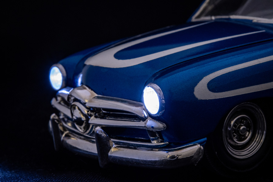
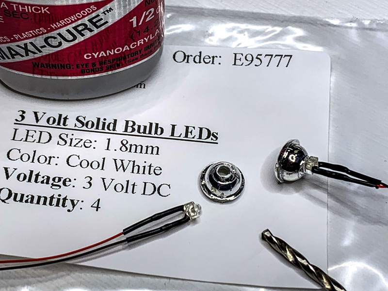
My latest project was an AMT/ERTL 1949 Coupe (Kit #6805) that I chopped, sectioned, and customized (more on that later). The front headlights are a simple chrome bucket with a clear plastic headlight, a perfect candidate for my lighting project. I ordered four 3 Volt Solid LEDS in a 1.8mm size (cool white color). Found a drill slightly larger than the LED bulb and drilled a hole in the center of the bucket. C/A super glues or five minute, two part clear epoxy was used to glue the bulb in place. Try not to get any on LED bulb. Once the glue has dried, paint the back side of the exposed bulb with silver paint. We don’t want the back of the bulb lighting up our front tire! To mount the taillight I had to drill out the body and glue the bulb in from behind, again painting the back of the bulb silver after the glue had dried.
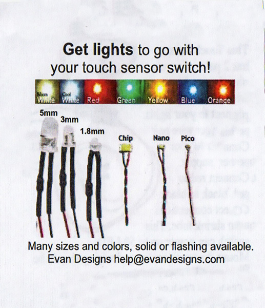
With the headlight and taillights glued in place I decided to try my luck at lighting the dashboard gauges. A single LED bulb would probably be enough to light the gauges from behind, but I wanted to experiment with Nano Chips these super small LEDs are known as surface mount LEDs, SMD LEDs, or Chip LEDs. They are very small and compact yet still very, very bright! The benefit of a flat and compact LED Chip, already wired for you, is that it still gives a great amount of light, but can be mounted flush, with no bulb shape showing. A bonus is the fact that the wiring for the Nano chips is very small and easy to route through tight spots!
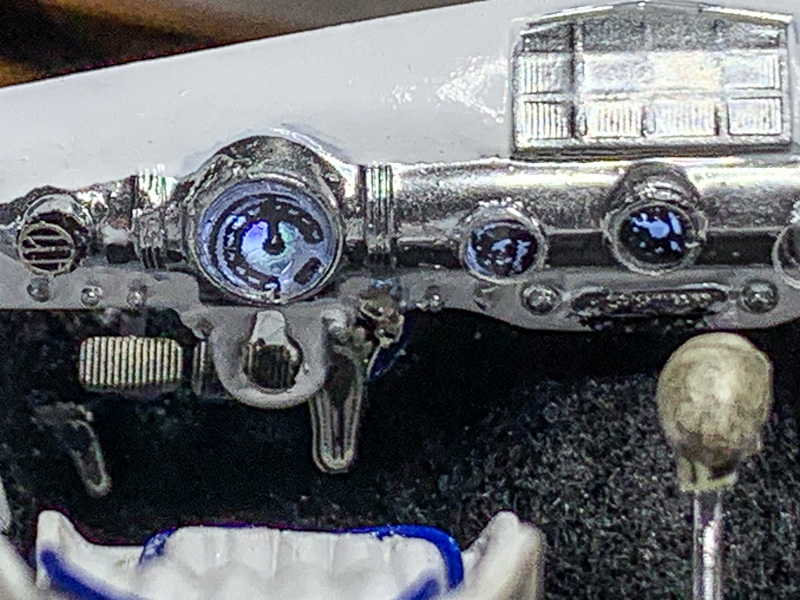
I started by drilling out the big gauge cluster on the dashboard, and the clock in the center of the dash. Then, just for fun, I drilled out two more holes (see photos) to add more gauges. A centerpunch was used to cut clear plastic to fit in the holes, and they were covered with gauge decals. By doing this it will allow the light to travel through the clear plastic and give the illusion of lighted gauges. To mount the Chip LEDs behind the dash I cut a piece of clear plastic to fit from behind. Then I used metal foil to hold the chips to the clear sheet. You don’t want to get any kind of glue on these chips! The two ends of the clear sheet were boxed in and everything sealed with chrome Bare-Metal foil. Just like the headlights you don’t want any light escaping and lighting areas that shouldn’t be. By mounting the chips on the clear plastic and then sealing it with the chrome foil there’s the bonus of the surface behind the chips are more reflective.
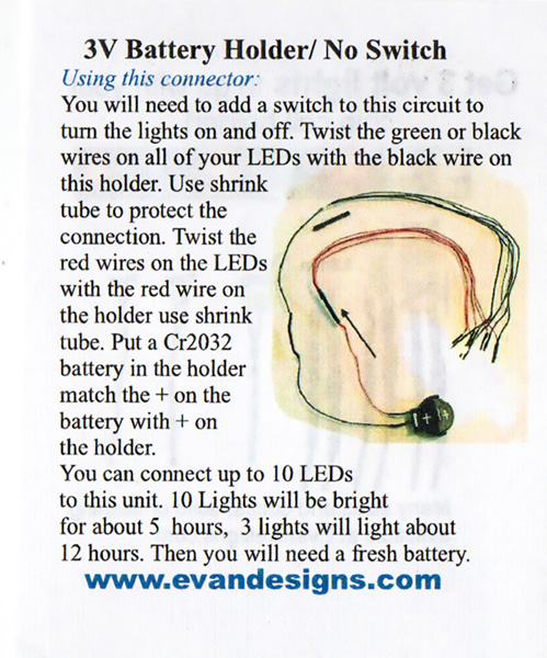
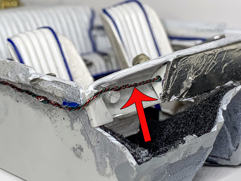
Now I needed a way to power the lights, and a way to turn them on and off with no bulky switch. The three volt power source was easy, a 3-Volt Coin Cell Holder is the answer. The flat watch battery can be hidden in the trunk of the car. But I also needed away to turn them on and off without a big, bulky switch visible. Luckily Evans Design sells Coin Cell Holder with a No Switch wire. Instead of the switch you have a small piece of exposed wire that you touch with your finger to turn the lights on or off. But where to hide the exposed wire? I opted on making it the emergency brake pull cable. There’s E-Brake cables that come from each rear brake drum backing plate and meet at the center of the car, then a cable comes from the E- brake pedal inside the car that pulls on the cables from the drums. This pull cable can be our on/off switch and no one would be able to tell it’s there!
I had one last problem to solve. Where to mount the switch controller and battery holder? I decided to glue the controller to back of the interior tub, and keep the battery clip in the trunk. But I had already painted the car, so it was too late to cut open and hinge the trunk lid. Instead I cut the gas tank/spare tire panel out of the chassis and then used earth magnets to hold thepanel in place (see photos). This way I can pop out the panel anytime I need to change the battery. So project challenged me because I don’t like any kind of wiring, but with help from Evan Designs I was able to accomplish exactly what I wanted to do in a minimal amount of time.
And now a few words about the car. The AMT ’49 Ford is one of those iconic cars that custom car builders just love to modify. I started with a simple top chop. I cut an 1/8th of an inch from the windshield pillars and the door pillars, then took a pie slice out of the back of the roof and leaned it down. A little adjusting of the pillars, trim the bottom of the windshield, and your top chop is done. But then the car screamed out for more. I used 1/4” wide masking tape wrapped around the car to mark where I wanted to section the body. Don’t forget to section the interior tub, firewall, and inner fender wells too! Once you’ve cut the section cut, glue the two halves back together, finish and paint. I make it sound a lot easier then it really is, but if I had to explain step-by-step then that would be another how to article!
For the interior we switched out the bench seat for bucket seats, and created tuck n’ roll upholstery using half round plastic strips. The motor is a 3D printed piece from Iceman Collections (https://icemancollections.com) and represents a modern Ford Coyote engine with a six speed transmission. Extra details under the hood include 3D printed brake master cylinder, OPTIMA dry cell battery, electric fan, and radiator overflow tank.
The car took about a month to complete, and I’m very happy with the final product.
RESOURCES
Evan Designs (lights and wiring)
1816B Heath ParkwayFort Collins CO 80524
Phone: 888-764-2610
Fax: 303-410-1118
Our Hours Mon-Fri: 9am - 3pm (MST)
Email: help@evandesigns.com
|
 |
Click to enlarge images or text above |
 |
| For our shoe box Ford I simply drilled out the kits front headlights to accept the LED bulb. |
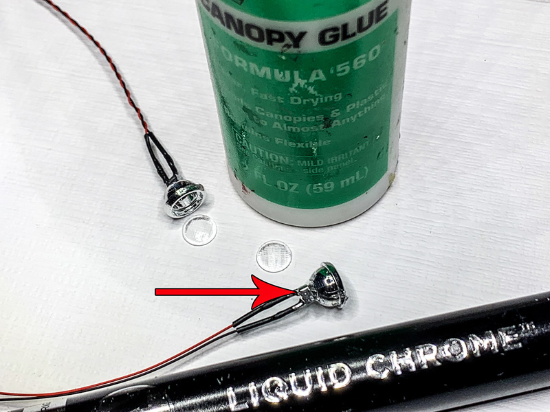 |
| I used 5-minute epoxy glue to fix the LED to the headlight bucket, and canopy glue for the clear lense. I then used a liquid chrome pin to seal the clear LED bulb back side. |
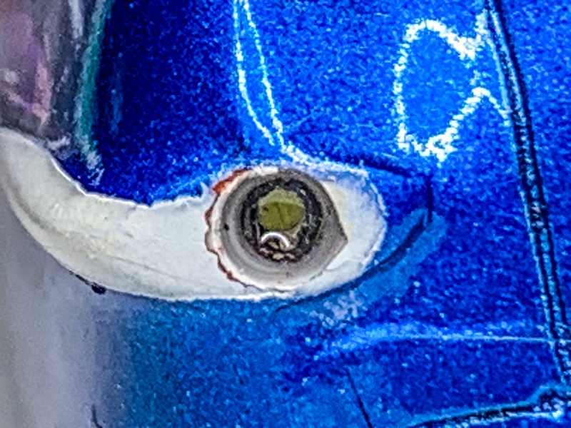 |
| At the back of the body I drilled out each tailight mounting hole. Than glued the LED in behind it. Since there is NO room in this fender for a regular LED bulb, I used an LED chip instead. |
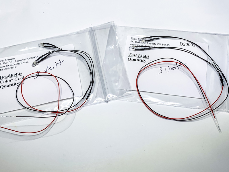 |
| Evan Design does offer this headlight/tailight combo as a kit. Don't worry the clear tail lights shown above turn red when lit. |
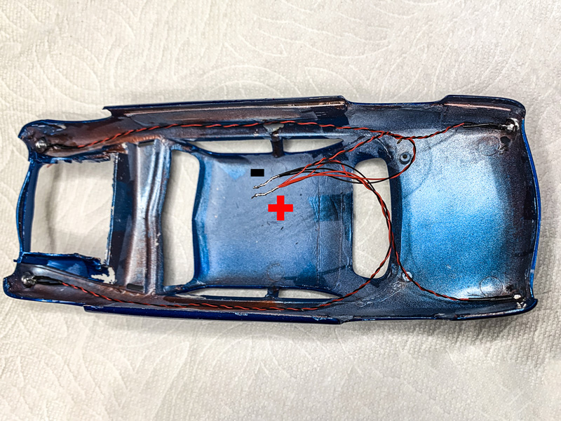 |
| The battery holder will be in the trunk. So the headlight wiring has to have long leads. Notice that I have twisted all the red wires together to form the positive side, and twisted all the black wires together to form the negative side. |
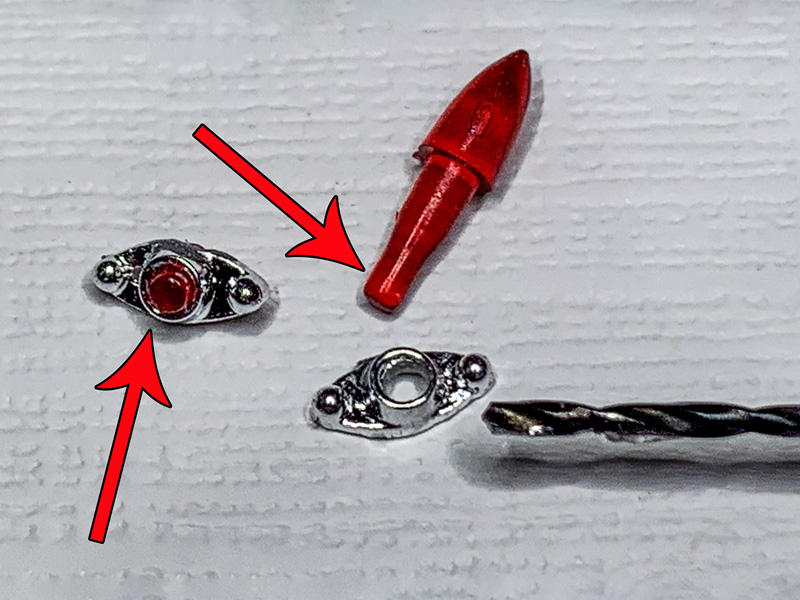 |
| The custom tailights from the kit had their centers cut out. Thand I dug through the spare parts box to find some round transparent red sprue to fill the holes. These mounting tabs on the back of some Caddy lights fit perfect. |
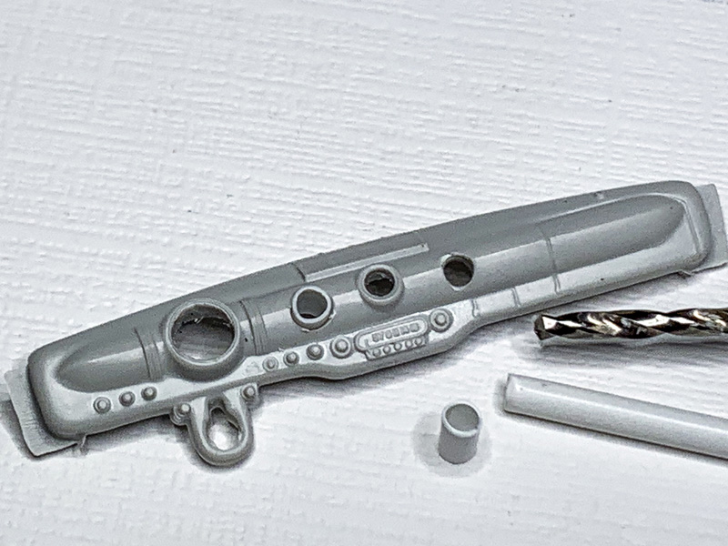 |
| I added a couple more gauges to the dash using a drill bit and Evergreen tubing. |
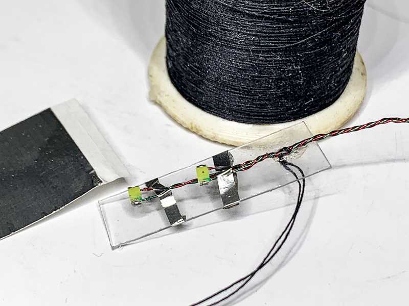 |
| LED chip lights are used to light up the gauges. Try not to get glue on the LED chips. I like to use clear plastic to form the light box that goes behind the dash, and... |
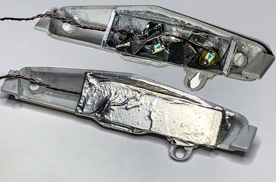 |
| ...use Bare-Metal Foil to seal it up. The foil is reflective and bounces the light. |
 |
| A small hole on one end of the box allows the wire to pass through. Feed the wire to the back of the car. |
 |
| Gauge decals were applied to clear plastic sheet for each gauge. |
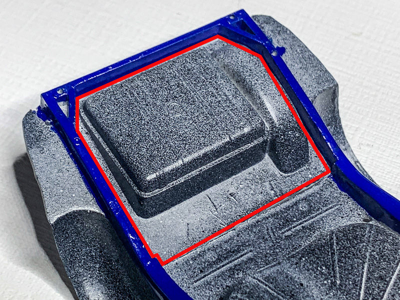 |
| To hide the battery case, but still make it accessible, I cut out the gas tank/spare tire. Scribe along the frame rail, and your cuts will be harder to see. |
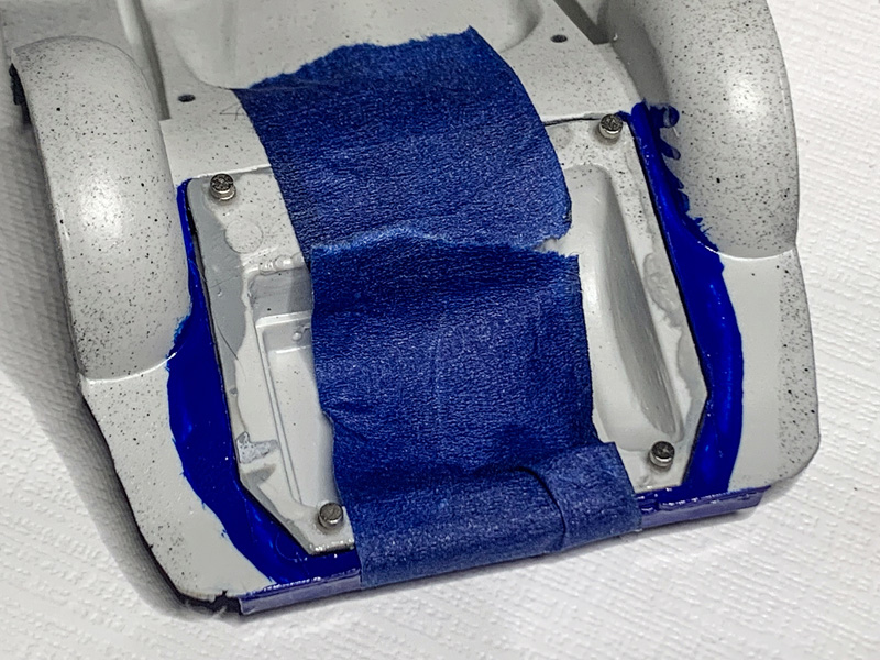 |
| I'm using small (but pwerful) earth magnets to hold the cover in place. I glued one magnet to each corner. After the glue dried a put a second magnet on top of the four magnets I had already glued down. Painter tape will hold things in place until I'm done building the mounting frame. |
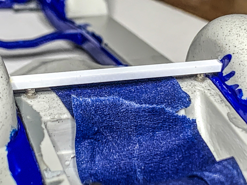 |
| The top bar is fairly easy because we have fenderwells to glue to. But before gluing in place, drop a small amount on each magnet as well (but don't let the glue reach the bottom magnet! |
| CLICK HERE FOR PAGE TWO |